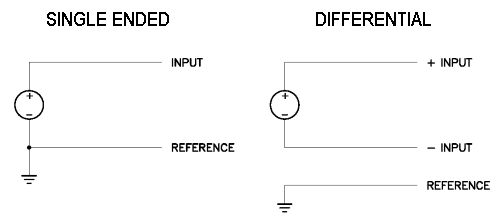
The analog inputs on an A/D board can usually be configured as either Single-Ended or Differential.
A single-ended input has one signal wire and one ground wire. The ground wire may be shared across multiple inputs. The A/D board measures the difference between the signal input and the ground, or reference.
A differential input has two signal wires and a ground wire. The A/D board measures the difference between the two signal wires, regardless of their voltage relative to ground.
| Type |
Single-Ended |
Differential |
| Wires | 2: Input and Reference | 3: Input+, Input-, and Reference |
| Noise immunity | Less | More |
| Input channels | More | Less |
| Wiring cost | Lower | Higher |
Differential inputs are used in two situations: (1) There is a possibility that electrical noise will adversely affect the quality of the signal, for example a low-voltage signal in a high-noise environment; and (2) The ground at the signal source is at a different potential than the ground at the A/D board, making it difficult to connect the two grounds together.
Differential inputs usually take up 2 input channels on an A/D board. This has a limiting effect on the number of channels the board can accept. Therefore most boards provide a means to select whether you are using single-ended or differential. Usually all the inputs must be of the same type. For example, a board with 32 single-ended inputs would let you configure it also for 16 differential inputs.
On the Diamond Systems Diamond-MM-32 board, however, you can select a "mixed mode" configuration, with 16 single-ended inputs and 8 differential inputs at the same time. This provides 24 total input channels, 8 more than you would get if you had to configure all inputs as differential.