This manual provides the information needed to use the JANUS-MM PC/104 carrier board, with dual CAN ports and provisions for installing a wireless modem and GPS module.
The manual includes:
The JANUS-MM is a PC/104 board that provides a complete single-slot I/O solution for mobile applications requiring a CAN bus interface, GPS receiver and wireless communications.
The board includes dual CAN controllers, and provides options for including a MultiTech SocketModemTM and / or a Trimble Navigation GPS receiver. The JANUS-MM product has the following features:
Depending on the application, the board can be configured for any of the following communication options. Jumpers are provided to configure the desired option.
Appendix A shows the available assemblies and development kits.
Appendix B lists the MultiTech SocketModemsTM compatible with the JANUS-MM board.
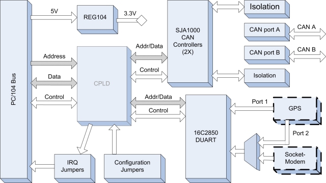
The board provides a standard PC/104 bus interface and dual CAN ports for interfacing to a CAN network. The dual CAN ports are opto-isolated, providing channel-to-channel and channel-to-system isolation.
Optional interfaces also support integration of a Trimble Navigation GPS and a wireless MultiTech SocketModemTM. The GPS and wireless modem interface to the system through an Exar 16C2850 dual UART. An external TTL-level modem port is also available when the SocketModemTM is not being used.
Figure 1 shows the JANUS-MM functional block diagram.
The board is designed for applications that can involve wireless communications and use positional information, obtained from a GPS receiver, to control devices connected on a CAN bus.
The UART is a dual port device that connects serial port 1 to a GPS receiver and serial port 2 to either a second GPS receiver or a SocketModemTM depending on the application. Refer to Appendix A for a list of configuration options.
A dual 16C2850 UART provides for the various configurations options. UART port 1 connects to one of the two GPS receiver serial ports and port 2 connects to either the second GPS serial port or to a SocketModemTM.
Jumpers are provided to configure board functionality, including IRQ selection.
The CAN bus interface, supporting CAN Specification 2.0 using the Philips SJA1000 CAN controller, implements the full CAN bus protocol.
The PC/104 bus connects to other stacked PC/104-standard components in the system, providing for CPU control of the board.

NOTE: Sockets are provided for the Trimble Navigation GPS and SocketModem.
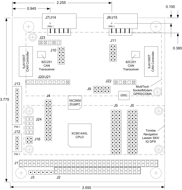
Figure 2 shows the board connector and jumper locations. (Major components are shown for reference). Connectors showing an ‘x’ in the pin position are keyed to assure correct module insertion.

The following table lists the connectors on the board.
| Connector | Description | Manufacturer Part No. |
| J1 | PC/104, ISA bus A,B | 2x32, press-fit |
| J2 | PC/104, ISA bus C,D | 2x20, press-fit |
| J3 | JTAG connector | 1x6, straight, 0.1" |
| J7 | CAN A port connector; 10-pin connector (replaces J14) | 2x5, right-angle, shroud, 0.1" |
| J8 | CAN B port connector; 10-pin connector (replaces J15) | 2x5, right-angle, shroud, 0.1" |
| J12 | GPS backup power and PPS signal | 1x4, right-angle, Friction Lock, 0.1” |
| J13 | Optional external modem access port | 1x10, right-angle, Friction Lock, 0.1” |
| J14 | Optional CAN A port connector; 5-pin connector (replaces J7) | 1x5, locking, 0.1” |
| J15 | Optional CAN A port connector; 5-pin connector (replaces J8) | 1x5, locking, 0.1” |
| J20-J23 | SocketModemTM Card | 1x5, straight, 2mm |
| J24 | GPS Receiver Card | 2x4, straight |
The following table lists the jumpers on the board.
| Jumper | Description |
| J4 | CAN Address selection |
| J5 | CAN IRQ selection |
| J6 | COM IRQ selection |
| J9 | UART port B connection and modem power configuration |
| J10 | CAN A power configuration |
| J11 | CAN B power configuration |
| J16 | GPS power selection |