Module Installation
This section describes the steps for installing the following components.
- MultiTech SocketModemTM module
- Trimble Lassen GPS modules
- PC/104 extender
Note: Always insure that you have a clean and clear work space and that you are properly grounded, wearing an anti-static wrist
strap.
MultiTech SocketModemTM Installation
Install the SocketModemTM before you install the Janus-MM card onto a PC/104 stack. You will need access to the bottom of the Janus-MM card to secure the standoffs in place.
Set all jumpers as required for CAN bus operation and to control the dual UART accessing the SocketModemTM BEFORE you install any modules on the Janus-MM board. If jumper changes are required, you will need to remove the module to alter the jumper settings.
If you intend to place a PC/104 card on the stack ABOVE the Janus-MM card after you have installed the SocketModemTM, you will also need to install a PC/104 Extender (DSC # 6801017) onto the Janus-MM card before installing the PC/104 card
above the Janus module. See PC/104 Extender Installation Instructions, below, for instructions on installing the PC/104 Extender.
- In the Janus-MM SocketModemTM Hardware Kit, DSC #680016, find the following items.
a. 2 each 4-40 x 3/16” Pan Head screws (DSC #681043)
b. 2 each 4-40 hex nuts (DSC #682041)
c. 2 each 4-40 x 7mm L hex M/F standoffs (DSC #684046)
- Place the female end of the 7mm hex standoffs through the mounting holes in the Janus-MM PCB shown in Figure 4, from the component side to the solder side, and secure each standoff with a hex nut on the solder side. Do not over-tighten.
- Place the SocketModemTM on the Janus-MM PCB so that the three connectors on the SocketModemTM match up with and insert into connectors J21, J22 and J23 on the Janus-MM module. Insure that the two mounting holes on the SocketModemTM line up with the top of the two hex standoffs. Press firmly to seat the SocketModemTM on the Janus- MM PCB.
- Install the two Pan Head Screws from the top side of the SocketModemTM through the SocketModemTM module mounting holes and into the hex standoffs. Tighten securely, but do not over-tighten.
- Install the antenna transition cable (DSC #6970012), if necessary, directly to the SocketModemTM antenna connector (See Figure 2). The antenna transition cable snaps into position.
- Attach the antenna, itself, (DSC # 6970011) to the antenna transition cable. The antenna screws onto the transition cable.
The SocketModemTM antenna transition cable connects to the antenna mounted on an enclosure. The enclosure cutout dimensions for the antenna mount are shown in Figure 3.
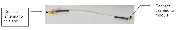
Figure 1: SocketModem Antenna Transition Cable (DSC #6970012)
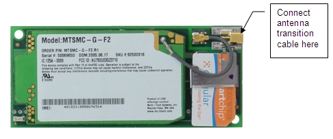
Figure 2: SocketModem Module

Figure 3: Panel (Bulkhead) Cutout for SocketModem Antenna Transition Cable
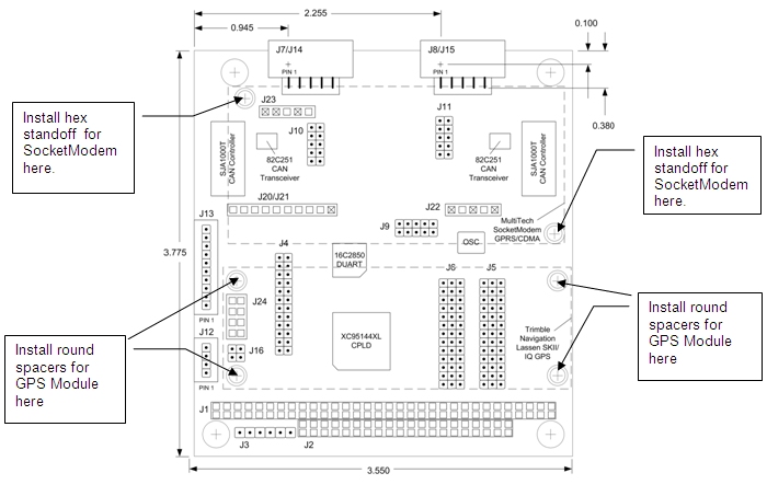
Figure 4: Janus-MM Board Layout
Trimble Lassen GPS Module Installation
Install the GPS Module before you install the Janus-MM card onto a PC/104 stack. You will need access to the bottom of the Janus-MM card to secure the spacers in place. These steps apply to both the GPS iQ and GPS SKII modules.
Set all jumpers as required for CAN bus operation and to control the dual UART accessing the SocketModemTM BEFORE you install any modules on the Janus-MM board. If jumper changes are required, you will need to remove the module to alter the jumper settings.
- Insure that jumper J16 is set correctly for the module you are going to install. For the Lassen SKIITM module, set J16 for 5v operation. For the Lassen iQTM module, set the jumper for 3.3v operation. Jumper settings for J16 are shown below.

Figure 5: J16 Voltage Selection
- In the Janus-MM GPS Hardware Kit, DSC #680015, find the following items.
a. 8 each 4-40 x 3/16” Pan Head screws (DSC #681043)
b. 4 each 0.25” OD x 0.12” ID Nylon Washer (DSC #683902)
c. 4 each 4-40 x 0.375”L round .187” Diameter spacers (DSC #684244)
- Place four pan head screws through the mounting holes in the GPS Module shown in Figure 7 and Figure 9, from the solder side to the component side.
- On the component side, place a single nylon washer over each screw.
- Screw one of the threaded round spacers onto each screw.
- Place the GPS Module on the Janus MM PCB so that the connector on the GPS Module match up with and insert into connector J24
on the Janus MM module. Insure that the four mounting holes on the Janus MM PCB line up with the top of the four round spacers. Press firmly to seat the SocketModem on the Janus MM PCB.
- Install the remaining four Pan Head Screws from the solder side of the Janus MM PCB through the PCB and into the round spacers.
Tighten securely, but do not over-tighten.
- Install the antenna transition cable, if necessary, directly to the GPS Module antenna connector. If you are using the Trimble Lassen SKIITM module, use transition cable DSC #6970003 (See Figure 6). If you are using the Trimble Lassen iQTM module, use transition cable DSC#6970002 (See Figure 8).
With the iQ module, the antenna snaps into a connector on the metal iQ component that is facing the PCB. Turn the module over and insert the antennae transition cable connector into the slot cut in the PCB. See Figure 10 for the location of the slot and the location of the connector on the iQ component. Figure 11 shows the transition cable installed on the iQ module.
The antenna transition cable snaps into position.
- Attach the antenna itself to the Antenna Transition Cable. For the Trimble Lassen SKIITM module, use the 5v antenna DSC #697001. For the Lassen iQTM module, use the 3.3v antenna DSC #697004.
The GPS antenna transition cable connects to the antenna mounted on an enclosure. The enclosure cutout dimensions for the antenna mount are shown in Figure 12, for the Trimble Lassen iQTM module, and Figure 13 for the Trimble Lassen SKIITM module.
Figure 6: Lassen SKIITM Transition Cable (DSC #6970003)
Figure 7: Lassen SKIITM Module
Figure 8: Lassen iQTM Transition Cable (DSC #6970002)
Figure 9: Lassen iQTM Module (Component Side)
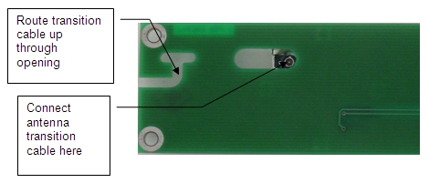
Figure 10: Lassen iQTM Module Solder Side (enlarged view; see below)
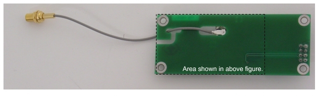
Figure 11: Lassen iQTM Module with Antenna Transition Cable Installed

Figure 12: Panel (Bulkhead) Cutout for Lassen iQTM Antenna Transition Cable

Figure 13: Panel (Bulkhead) Cutout for GPS SKII Antenna Transition Cable
PC/104 Extender Installation Instructions
Note: These installation apply to stacked systems, where the Janus-MM board is not the top board in the stack.
Follow these steps to install the PC/104 extender, which allows you to mount an additional PC/104 board on top of the stack
without a component conflict with a GPS or SocketModem module.
- In the PC/104 Extender Hardware Kit (DSC #6801017) , you will find the following:
a. 1 each 40-pin (2x20) PC/104 expansion header
b. 1 each 64-pin (2x32) PC/104 expansion header
c. 8 each 4-40 x 0.6” L M/F round standoffs
d. 5 each 0.25” OD x .12” ID x .062 T nylon washers
- Install the Janus-MM board with modules installed on the PC/104 stack
- Insert the 40-pin PC/104 expansion header into the 40-pin PC/104 connector (J2) on the Janus-MM board.
- Insert the 64-pin PC/104 expansion header into the 64-pin PC/104 connector (J1) on the Janus-MM board.
- Screw one 0.6” round standoff into each of the four PC/104 mounting holes. The round standoffs will go through the Janus-MM board and screw into the standoff below the Janus-MM board.
- For each of the four remaining standoffs, place a single nylon washer on the female end of each standoff and screw the standoff
directly into the top of each standoff protruding from the Janus-MM board. The washer matches the thickness of a PC/104 board.
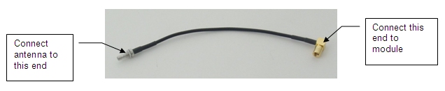 Figure 6: Lassen SKIITM Transition Cable (DSC #6970003)
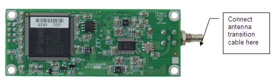 Figure 7: Lassen SKIITM Module
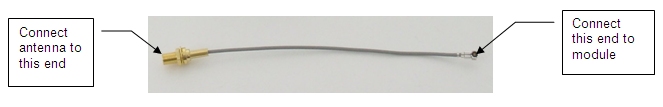 Figure 8: Lassen iQTM Transition Cable (DSC #6970002)
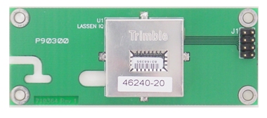 Figure 9: Lassen iQTM Module (Component Side)