3.5" Form Factor

PC/104

PC/104-Plus

PCIe/104

PCI/104-Express

COM Express

Single Board Computers

I/O Modules

Power Supplies

Single Board Computers

I/O Modules

Power Supplies

I/O Modules

Single Board Computers

Cables

PC/104

Adapters

PC/104

PC/104-Plus

PCIe MiniCard

PC/104

PCIe MiniCard

PC/104

PC/104-Plus

PCI/104-Express

PCIe MiniCard

PC/104-Plus

PCIe MiniCard

PC/104-Plus

PCIe MiniCard

I/O Modules

Single Board Computers

I/O Modules

PC/104

PC/104-Plus

PC/104

Small form factor

Ethernet Switch Modules

Single Board Computers

Ethernet Switches

AGX Orin Solutions

ORIN Nano / NX

Nano and NX Solutions

AGX Xavier Module Solutions

TX2 / TX2i Module Solutions

Whitepapers

Designing Embedded Computers for Rugged Applications

Application Articles

Building Automation
Paper Processing
Train Controller
Wind Instrument
Lung Simulator
Gas Analyzer
Weapon System

Visit our Markets & Applications page.

Sign Up for our eNewsletter Today!


A/D Board Tutorial
Slideshow Contents
Introduction
Typical A/D Board Architecture
A/D Chip Technology
Resolution and Input Range
Input Bandwidth
Input Channel Configurations
Differential Input Simulation
A/D Sampling Methods
A/D Triggers
Sampling Sequences
Data Transfer to Memory
Interrupt Timing
Source Impedance
Source Impedance - Solution
Calibration
Autocalibration
Comparison Test: Autocalibration vs. Manual Calibration
Results: Autocalibration vs. Manual Calibration
<-prev next->

Sampling Sequences


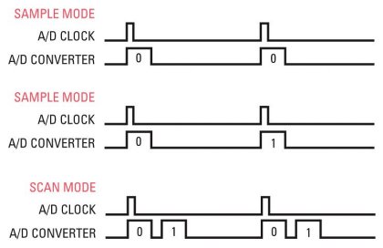
The upper illustration shows single-channel sampling mode. In this mode a single channel is sampled, either once or repeatedly with regular timing.

The middle illustration shows multi-channel round robin sampling. In this mode multiple channels are being sampled in a rotating sequence. One channel is sampled on each A/D trigger. This is a simple way to manage multi-channel applications and is typical of a lower-end A/D board. Note that the sample rate for each channel is equal to the A/D clock rate divided by the number of channels being sampled. You must take this ratio into account when determining your sample rate. Also remember to make sure that the number of samples you take is equal to a multiple of the number of channels being sampled.

The lower illustration shows multi-channel scan sampling. In this mode multiple channels are sampled in quick succession on each A/D trigger. The channels being sampled are determined during the board setup or in the software driver function call. Usually any sequential group of channels can be set up for scan mode, for example channels 0-1, 0-15, or 3-9. This is a more advanced architecture that simplifies application development since it eliminates having to worry about whether the number of A/D clocks or number of samples taken is a multiple of the number of channels being sampled.