|
 |
Description |
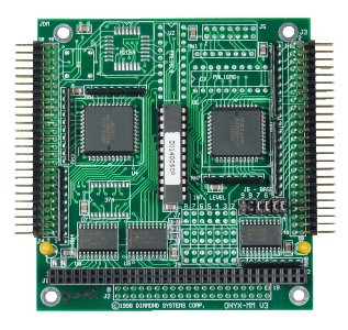
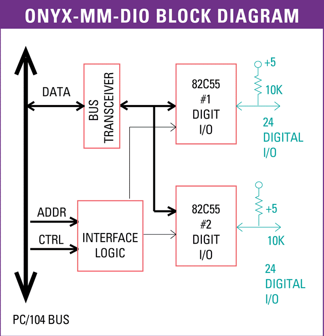
Onyx-MM-DIO has 48 digital I/O lines using 2 82C55 ICs. Each chip has 24 I/O lines organized as three 8-bit ports, A, B, and C. All I/O lines are connected to 10KOhm pull-up resistors, and on power-up or system reset, all ports reset to input and are pulled high. A control register on the 82C55 chip allows you to program each port for input or output and for different operating modes, including basic I/O, strobed I/O, and bit set/reset.
Mode 0 operation provides basic input and output operations. No handshaking signals are used. This is the most common method of digital I/O and is useful for reading status signals, turning switches on and off, etc. All three ports can operate in Mode 0.
Mode 1 operation provides strobed I/O on ports A and B with handshaking signals provided on port C. In input mode, one signal is a strobe to latch data into the port, and a second signal is an acknowledge output. In output mode, one signal is used to indicate that the CPU has written new data to the port, and a second signal is an acknowledge input.
Mode 2 operation allows the use of Port A as a bidirectional data bus, with port C lines used for handshaking. Port A is normally in tristate mode. When the CPU writes new data to port A, an output signal indicates new data is available. In response, the external circuit strobes an acknowledge input signal, thereby enabling the output buffers on Port A. The external circuit can also latch new data into Port A with an input data strobe signal.
Bit set/reset mode enables individually setting (1) or resetting (0) any bit on Port C without having to read Port C and mask or protect unaltered bits.
Diamond's free Universal Driver software provides a comprehensive C programming library to control all the digital I/O features. Example programs are included with both source code and executables to assist you in developing your application quickly.
 |
I/O Header Pinout |
Onyx-MM-DIO contains 2 50-pin I/O headers with 24 I/O lines organized as 3 8-bit ports on each header. 5V power and Ground pins are also provided on each header.
|
J3 (Right Side)
| (Port A) A7 |
1 |
2 |
Ground |
| A6 |
3 |
4 |
Ground |
| A5 |
5 |
6 |
Ground |
| A4 |
7 |
8 |
Ground |
| A3 |
9 |
10 |
Ground |
| A2 |
11 |
12 |
Ground |
| A1 |
13 |
14 |
Ground |
| A0 |
15 |
16 |
Ground |
| (Port C) C7 |
17 |
18 |
Ground |
| C6 |
19 |
20 |
Ground |
| C5 |
21 |
22 |
Ground |
| C4 |
23 |
24 |
Ground |
| C3 |
25 |
26 |
Ground |
| C2 |
27 |
28 |
Ground |
| C1 |
29 |
30 |
Ground |
| C0 |
31 |
32 |
Ground |
| (Port B) B7 |
33 |
34 |
Ground |
| B6 |
35 |
36 |
Ground |
| B5 |
37 |
38 |
Ground |
| B4 |
39 |
40 |
Ground |
| B3 |
41 |
42 |
Ground |
| B2 |
43 |
44 |
Ground |
| B1 |
45 |
46 |
Ground |
| B0 |
47 |
48 |
Ground |
| +5V |
49 |
50 |
Ground |
|
|
J4 (Left Side)
| (Port D) D7 |
1 |
2 |
Ground |
| D6 |
3 |
4 |
Ground |
| D5 |
5 |
6 |
Ground |
| D4 |
7 |
8 |
Ground |
| D3 |
9 |
10 |
Ground |
| D2 |
11 |
12 |
Ground |
| D1 |
13 |
14 |
Ground |
| D0 |
15 |
16 |
Ground |
| (Port F) F7 |
17 |
18 |
Ground |
| F6 |
19 |
20 |
Ground |
| F5 |
21 |
22 |
Ground |
| F4 |
23 |
24 |
Ground |
| F3 |
25 |
26 |
Ground |
| F2 |
27 |
28 |
Ground |
| F1 |
29 |
30 |
Ground |
| F0 |
31 |
32 |
Ground |
| (Port E) E7 |
33 |
34 |
Ground |
| E6 |
35 |
36 |
Ground |
| E5 |
37 |
38 |
Ground |
| E4 |
39 |
40 |
Ground |
| E3 |
41 |
42 |
Ground |
| E2 |
43 |
44 |
Ground |
| E1 |
45 |
46 |
Ground |
| E0 |
47 |
48 |
Ground |
| +5V |
49 |
50 |
Ground |
|
 |
Block Diagram |
 |
Cables |
Onyx-MM requires 2 cables for the 48 GPIO signals. Each cable provides 3 8-bit ports along with +5V and ground connections.
| Cable |
Description |
Drawing |
| C-50-18 |
50-conductor .1" pitch 18" ribbon cable, Data acquisition Cable (Each board uses 2) |
Show |
 |
Specifications |
| Digital I/O |
| Chip |
82C55A (qty. 2) |
| Number of I/O lines |
48 |
| Direction |
Programmable in groups of 4 or 8 |
| Input voltage |
|
| Low: |
-0.5V min, 0.8V max |
| High: |
2.0V min, 5.5V max |
| Output voltage |
|
| Low: |
0.0V min, 0.4V max |
| High: |
3.0V min, Vcc -0.4V max |
| Output current |
2.5mA max, each line |
| Pullup resistors |
10KΩ all input lines |
| General |
| Power supply |
+5V 10% @ 100mA typical, all outputs open |
| Temperature |
-40°C to +85°C |
| PC/104 Bus |
8 bits |
| Weight |
2.3 oz/65g |
| MTBF |
OMM-DIO-XT 1,714,901 hours |
| RoHS |
Compliant |
|


