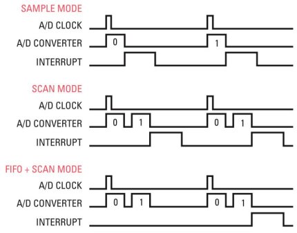
This illustration shows three different sampling methods with interrupts.
The upper diagram shows single-channel sampling with interrupts. Each A/D trigger generates one A/D sample on one channel and one interrupt. This is the simplest method that involves the most software overhead. This method will only work up to about 1KHz in operating systems such as Linux or Windows due to the extreme interrupt overhead required. (DOS will support interrupt rates up to about 20KHz, depending on the duration of the interrupt routine.) Remember in this mode the sample rate for each channel is equal to the A/D clock rate divided by the number of channels being sampled, so for multi-channel applications the maximum sample rate for each channel will be severely limited.
The middle diagram shows multi-channel scan sampling with interrupts. Each A/D trigger generates a sample on all selected input channels. At the end of the scan a single interrupt causes the entire scan to be transferred to memory. This reduces the interrupt rate by a factor equal to the number of channels being sampled (in this case 2). This is an improvement over the above method but still not optimal.
The bottom diagram shows multi-channel scan sampling with interrupts and FIFO support. This is the most advanced method of sampling and provides the best performance. The interrupt rate is reduced by the size of the FIFO threshold, resulting in a dramatic reduction in interrupt overhead. For example, a total sample rate of 200KHz and a FIFO threshold of 300 results in an interrupt rate of only 667Hz, easily manageable by almost any operating system.


 prev
prev